What a network floor plan should show your installer
Turn a conceptual design into a useful field document with racks, pathways, drops, labels, and power.
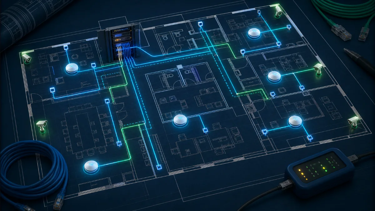
A device dot is not an installation instruction
Concept drawings communicate intent; field drawings remove ambiguity. A useful plan is scaled, oriented, versioned, and tied to a legend. It distinguishes device types and gives each item a unique identifier that follows it from cable pull through testing and final documentation.
Show locations precisely
Dimension devices from stable architectural references such as walls, grid lines, or door frames. “Center of room” is ambiguous when ceilings contain lights, diffusers, beams, or access panels. Note mounting height, orientation, surface, bracket, weather rating, and any requirement for a back box or pendant.
- Unique device and cable ID
- Horizontal position and mounting height
- Camera direction or AP mounting orientation
- Ceiling, wall, pole, rack, or junction-box detail
- Access and service-clearance constraints
Show the complete cable story
Identify the originating rack, destination, media type, pathway, and approximate length. Mark transitions between tray, conduit, sleeve, and open ceiling. Call out backbone links, fiber type, strand count, patch panels, and intermediate distribution rooms. The drawing should expose overlength runs before cable is pulled.
For powered endpoints, document the switch and PoE requirement. Access-control drawings also need lock, reader, sensor, request-to-exit, and power relationships—not only an icon beside the door.
Coordinate with the building
Network routes share space with electrical, mechanical, fire protection, structure, and architectural finishes. Flag penetrations, firestopping, exterior transitions, grounding, lift requirements, ceiling access, and work-hour limitations. Reference applicable codes and project specifications; do not rely on a network plan to replace a licensed life-safety or electrical design.
Close the loop with as-builts
The final drawing should reflect what was installed, not what was originally intended. Update device positions, cable IDs, rack elevations, port mappings, pathway changes, and test results. Pair the drawing with configuration backups and an asset list.
Good documentation reduces future troubleshooting from hours to minutes and makes the next expansion safer to plan.
DesignNerd is built by The UniFi Nerds, the nation's leading UniFi installation and managed services company.