Why wall materials matter in a WiFi heatmap
Concrete, glass, brick, drywall, wood, and metal do not affect RF equally. Here is how to model them.
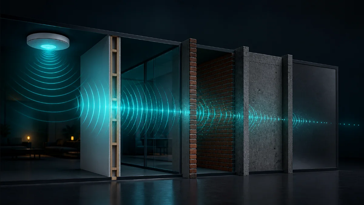
Distance is only part of indoor propagation
Free-space loss explains how signal weakens with distance, but buildings add absorption, reflection, scattering, and multipath. A short path through reinforced concrete may be worse than a much longer path across an open office. Treating every line on a floor plan as generic drywall produces attractive but misleading coverage.
Frequency also matters. A material does not impose one universal loss value across 2.4, 5, and 6 GHz, so a single blended heatmap can conceal higher-band dead zones.
Model what is actually in the wall
Architectural drawings may show wall type codes that reveal layers, studs, insulation, tile, fireproofing, or reinforcement. Use that information when available. A concrete core, metal-backed insulation, elevator shaft, storage rack, low-emissivity glass, or tiled wet wall can materially change the design.
Do not trace every line. Furniture outlines and annotation marks are not RF barriers. Focus on full-height construction and large objects that meaningfully alter propagation.
Use material values as estimates
Published attenuation values vary because thickness, moisture, density, reinforcement, angle, and construction details vary. A “brick wall” may be veneer over studs or multiple structural wythes. A glass partition may be ordinary interior glazing or coated exterior glass.
Use conservative defaults during prediction, then measure representative walls when the project warrants it. Compare signal on both sides with a stable AP and client or survey tool, and adjust the model to reflect the actual site.
Watch for cumulative loss
One partition may look harmless, but a diagonal path can cross several walls before reaching a client. Small losses accumulate, and oblique angles increase the distance traveled through a material. APs placed in corridors often look central while asking signals to cross multiple walls into every room.
Place APs with line-of-sight or minimal obstruction to the users who need the most reliable service. Dense rooms may deserve their own AP even when a distant hallway AP appears visible.
A practical modeling checklist
Build the model in layers and inspect the result band by band. The goal is not photorealistic drafting; it is representing the barriers that change placement decisions.
- Confirm plan scale before drawing walls
- Trace exterior walls, cores, shafts, and full-height partitions
- Separate glass, drywall, brick, concrete, wood, and metal
- Account for storage racks and other large dense obstructions
- Check diagonal paths through multiple barriers
- Calibrate unusual materials with on-site measurements
- Validate the installed network and retain the corrected model
DesignNerd is built by The UniFi Nerds, the nation's leading UniFi installation and managed services company.